
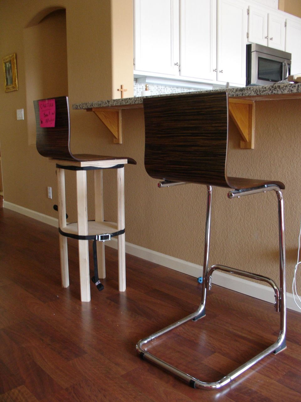
 Designing a new project from scratch is a wonderful albeit frustrating process. Making mockups from cardboard, foam core, masonite, etc. is a great way to supplement scale drawings but sometimes you don’t really see what you have until you have it. Now if that sounds convoluted it probably is! You can get the gist of a design from all of those methods but until you get the first prototype built those little details don’t surface. This picture is what I believed would be the final design. If you’ve been following along you’ll recall that this is the second mock up. The first one had too small of a tipsy footprint so I increased the diameter of the discs from 12″ to 14″. With this example the height has been determined, it’s just under 2″ taller than the original.
When creating a project it’s always wise to put it together and in its’ environment so you can study how things look. A few things weren’t exactly right to my and Diane’s eye. First of all, the legs are too bulky and the radiused edge gave an appearance that was, to quote Diane “too much like the sixties” and although that’s when I grew up the retro look isn’t what I’m after. The legs are now closer to square at 1 1/2″ and will taper to something like 7/8″ square at the bottom of each leg. Making the discs was a time consuming process.
To make them I used a small plunge router with a 1/4″ upcut spiral bit. This process makes an enormous amount of dust! I discovered that after making just two of them for the prototype. Luckily it was garbage day so I had two, empty cans to use as supports for half of my assembly table. I set it up on the side of the house.
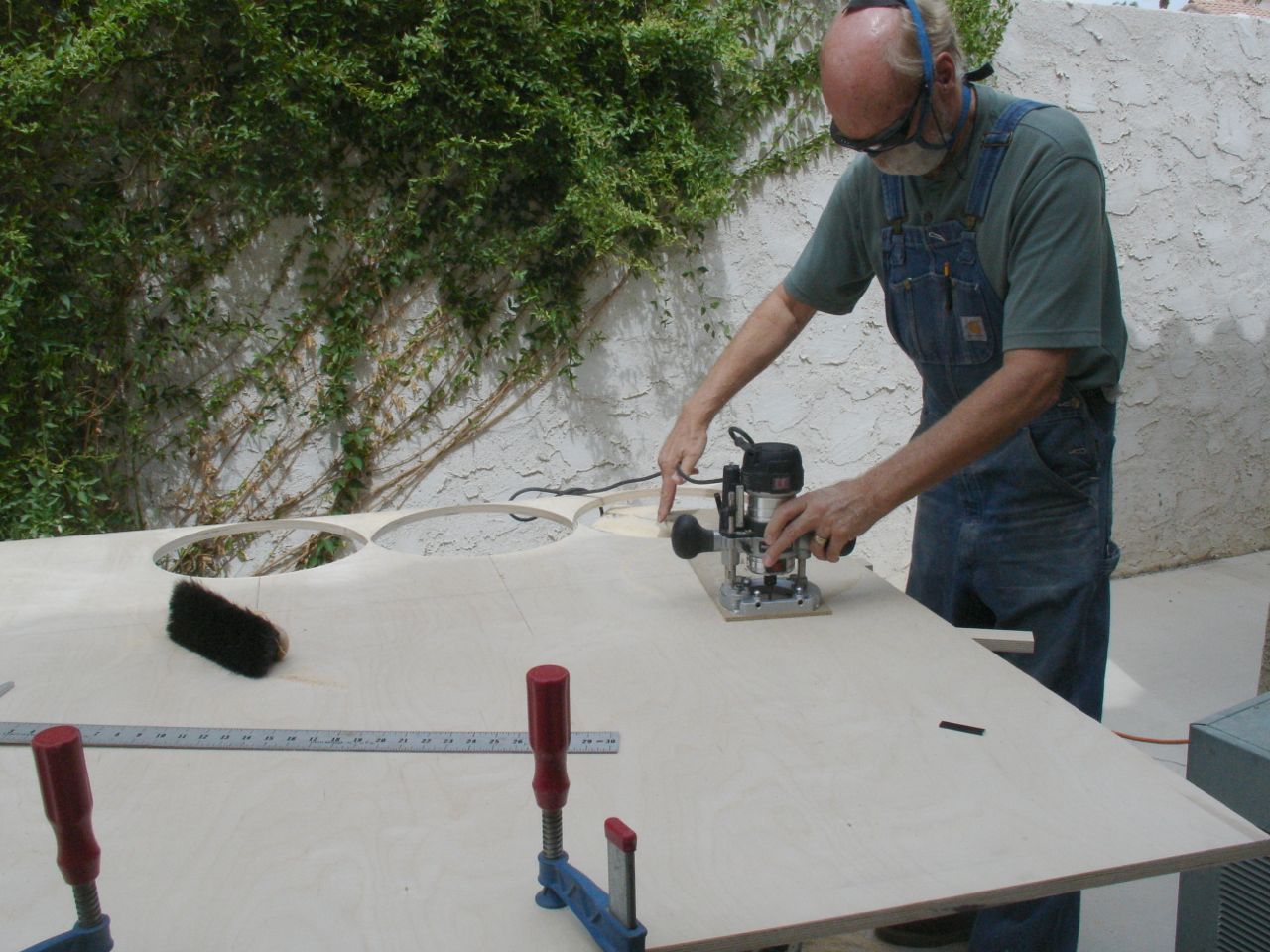 Dust mask, ear plugs, and safety glasses a must for this process. The turret on the plunge router has 1/4″ steps but that was too much of a cut to take in one pass. Instead, I used a 1/8″ set up block from Veritas so that each pass was only 1/8″ deep. May take longer but there is less wear and tear on not only the router but also the bit. That means that each disc took 6 passes to cut out — I needed a total of 8. Next up was to cut flats on the outside of them that are 90 degrees apart. They’re needed so that there is a flat spot on the disc to seat into the leg. A bit of a head scratcher but here’s the solution. Each disc has a 3/16″ hole in it so that was incorporated into a jig that rides against the rip fence on the table saw. The first cut is lined up with the center line and then the disc is rotated 90 degrees until is is square to the side of the jig. These pictures will help to explain that, you can click on each image to enlarge:
-
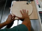
- Initial cut lined up with Center Line
-
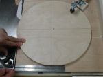
- Disc rotated and squared to first cut
The final step for the discs was to remove the center of the bottom ones. These will become the footrest for the stool. Another hole was drilled into the circle cutting jig about 2″ smaller to create this ring. The thing to keep in mind is that now, when the cut is all the way through, there’s the possibility of moving the cutter into the ring when it breaks free. To avoid that problem you should nail both of them to a piece of scrap like this: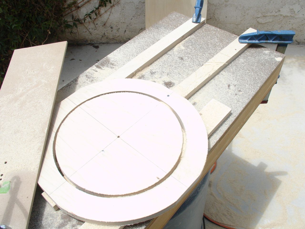
See the nail at the top of the ring and also close to the center point? Since both pieces are anchored to the scrap below you minimize the risk of cutting into the ring. All that remained was to put a slight radius on all exposed edges. Since this is the “foot rest” it needs to be eased slightly to avoid splintering.
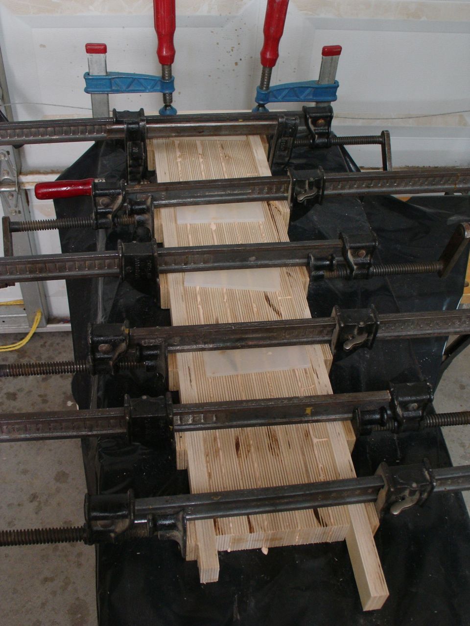
The remaining time was spent on laminating the rest of the leg stock together. I could do 4 legs at a time and used this set up to hold them square.
