What the Heck ??
Jamie, from Wooditis where I occasionally teach classes, referred a couple to me who were looking for someone to make a presentation box for an item they are marketing. We had the usual email correspondence and then met twice to explore the possibilities of bringing what they have in mind to an actual piece. What adds to the intrigue of this is that things must be kept somewhat secretive! It’s an item that they have developed and successfully marketed overseas and now they want to get themselves into the high end retail areas of our Las Vegas Strip. They came prepared with drawings and measurements of what they require and also some photographs of the types of presentation boxes that could be comparable to what they’d like to have. After working out the details the best we could an agreement was reached and I told them I’d start work on their idea. On paper everything seemed to be okay although I did have some concerns once I really plotted out the overall size of the box. Seeing the over-all size scaled out in a drawing showed me that this box is larger in scale than I though it would be. We had decided to use Wenge but at around $20.00 a board foot I thought it may be wise to make a prototype utilizing some other material first.
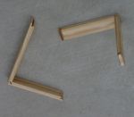
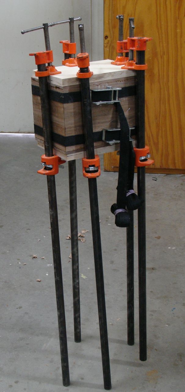
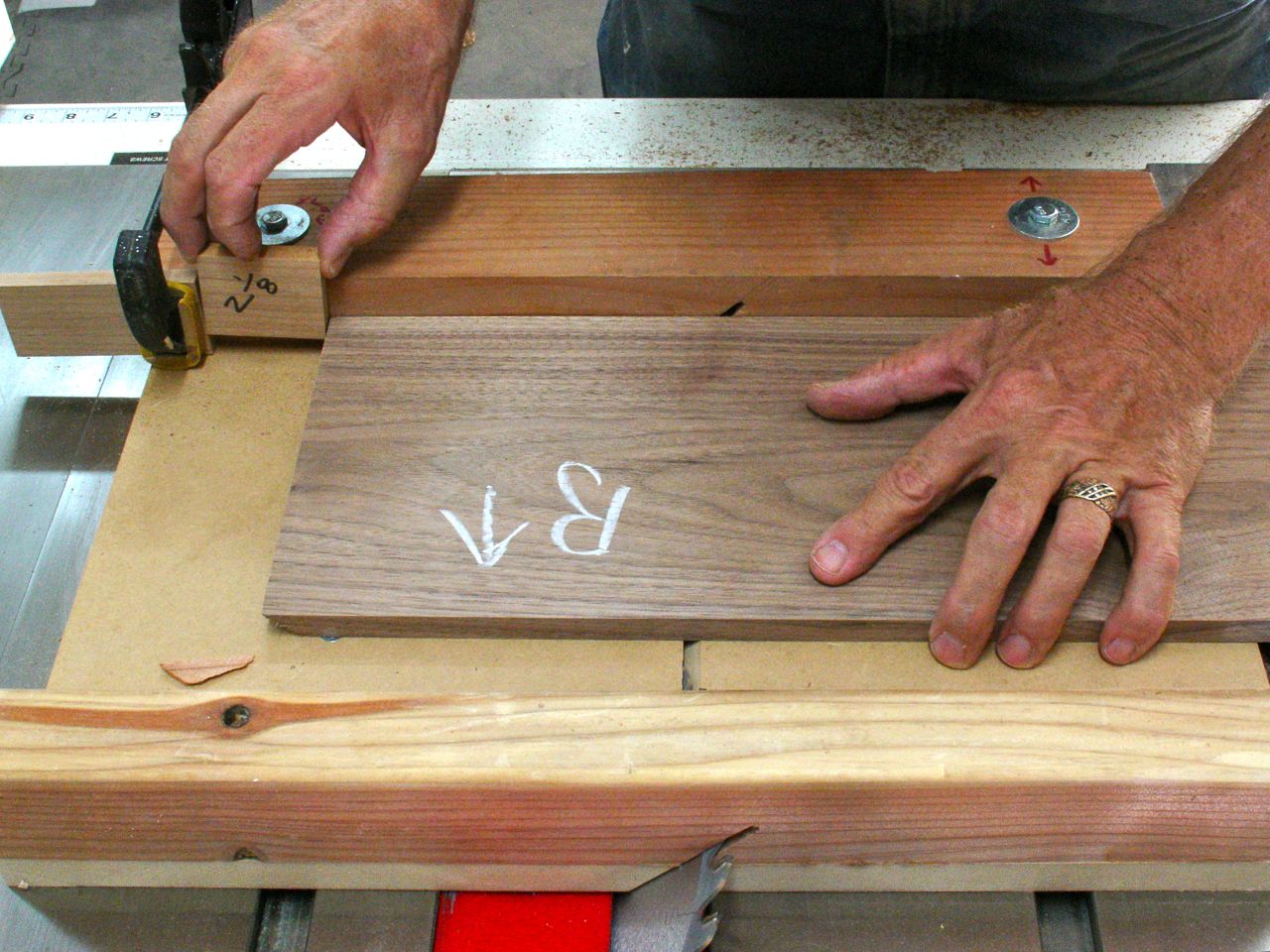
Looking through my lumber, I discovered a piece of Walnut that was just about the correct size so I went ahead and worked the prototype out with it. That’s what the picture is; two band clamps plus cauls top and bottom to make a cube that will be cut apart to form a deep box with a shallow, clamshell style lid. The design for the lid has it unevenly split to provide storage space for items needed. Things started conventionally enough. After setting the tablesaw to 45 degrees the pieces for the sides were cut to length. My method is to set a stop block for the longest piece, then use a spacer to cut the shorter one. The size of the spacer is the difference in the length of the two pieces, in this case the spacer measured 2 1/8″.
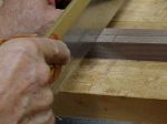
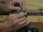
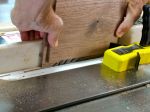
 The purpose of following this procedure is so the grain on the box is continuous all the way around. You can’t simply cut both long pieces, reset your stop block and then cut the two shorter pieces. The grain won’t continue, that’s why there is the chalk marking to indicate the order of the piece and also the direction it should be oriented during glue up. Next up was to make the lid. The design calls for a seamless lid that is solidly glued to the entire box — I know what you’re thinking; what about wood movement? There is a man on Lumberjocks who uses the name of Boxguy who uses this method. I’ve had some correspondence with him and he assures me he’s been doing this for 10 years and never had a problem, he thinks it’s because the small size of his work doesn’t have enough wood movement to affect it. This possibility was discussed and we decided to go ahead with this for the Mystery Box. To create the 1/2″ rabbet all around the top and bottom pieces I used the table saw as shown below to rough it out which was followed by accurately sizing it with a rabbet block plane.
-
-
Tablesaw for Approximate Size
-
-
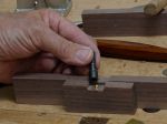
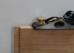
Rabbet Block Plane for Exact

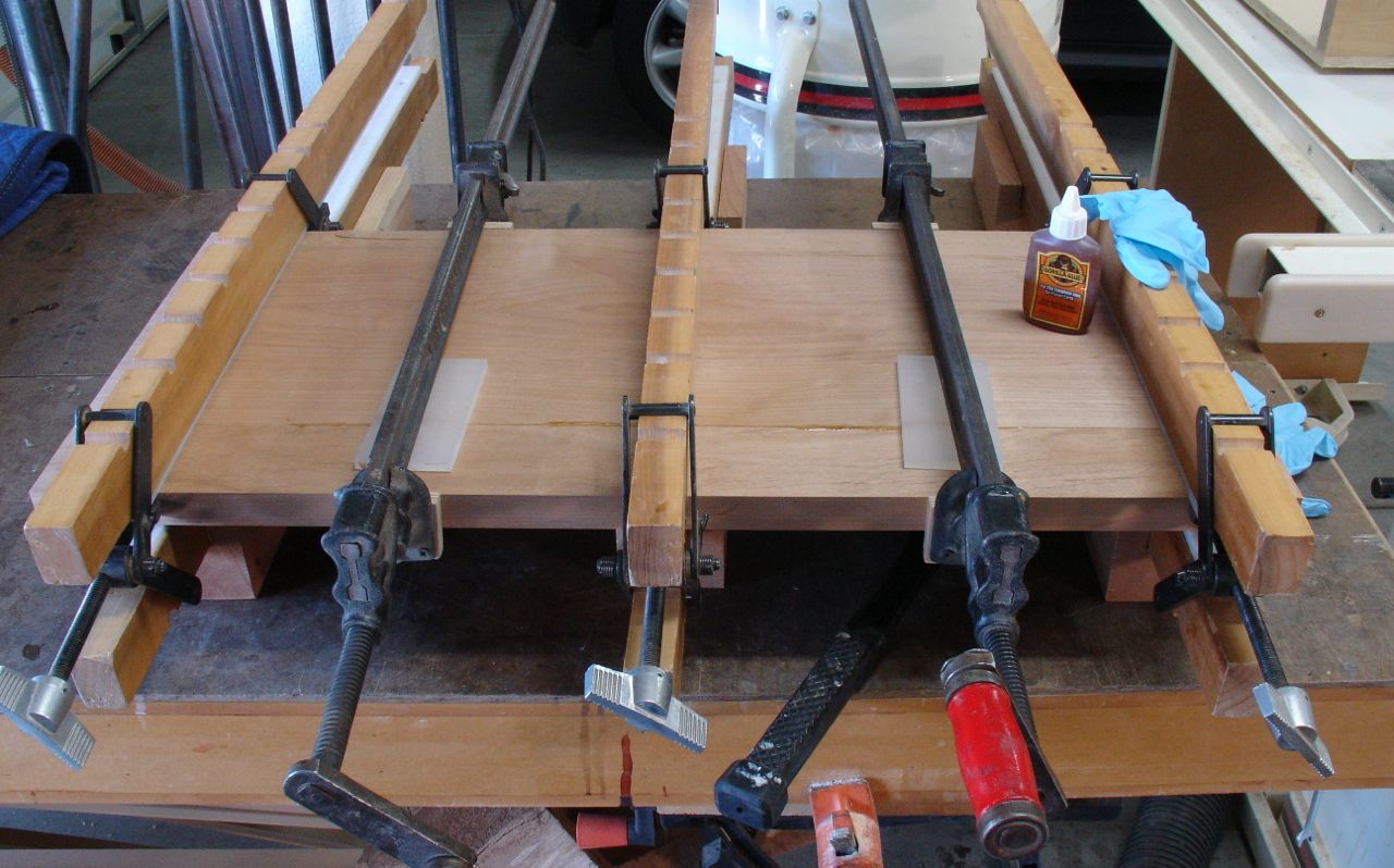
Assembly was started by applying two rows of packaging tape to hold it together initially followed by two band clamps. Once that was together the top and bottom were attached and clamped like the picture at the top of this blog. Kind of looks like a modern art sculpture in that photo doesn’t it?
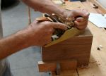
Entire piece was allowed to dry overnight and then began the process of making this look like the examples they had shown me. The inspiration for them was some leather bound ledgers and had something to do with the bottle of liquor it held. The inside depth specified for the lid was 1 1/4″ and this lid was to be a 1/3 — 2/3’s split. Before separating them though I used planes to smooth out the surfaces and edges.
-

-
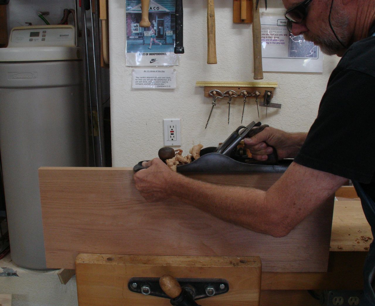
Block Plane for End grain
-
-
Smooth Plane for Face grain
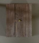
My first cut was to divide the lid part way down with the tablesaw and then complete it by hand. Next would be to separate the lid from the rest of the box. This is commonly done with the tablesaw and my technique is to cut the two long sides completely through, then lower the blade to leave a sixteenth of an inch or so that can be cut by hand. This eliminates the problem of having the lid bind as the cut is complete.
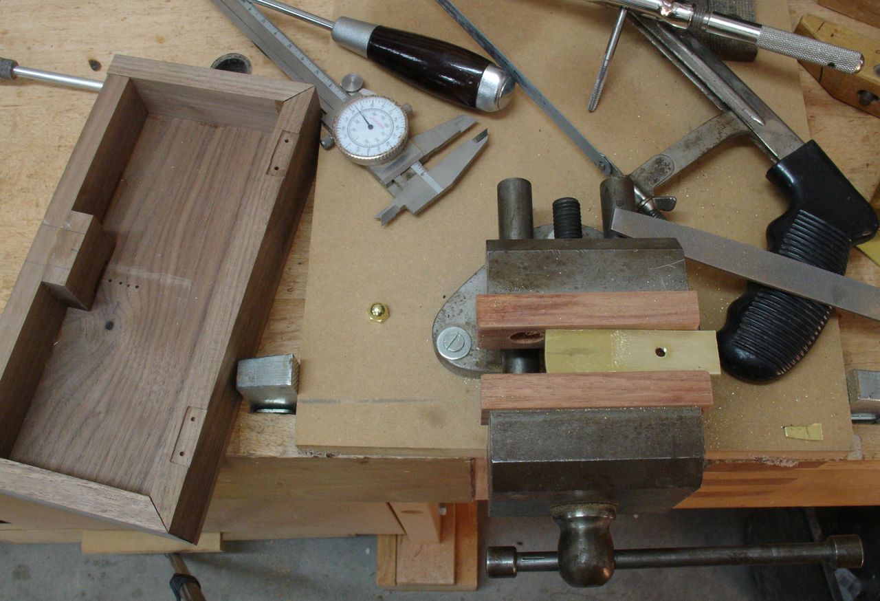
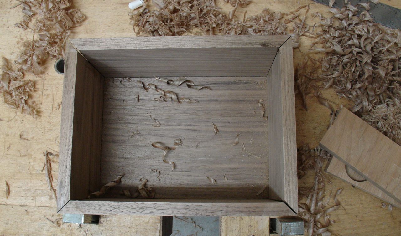
This is where the problem began! As I was making these cuts I could hear some cracking — never a good sound when working wood! Sure enough, when I finished the cut here’s what I found:

You can see that when the piece was separated the stresses that were inherent to the wood let go. In the photo, the upper left and lower right corners have separated. This confirms my concerns that for a box of this size the mitered joint is not a good solution. Possibly adding a spline to reinforce it will be an option. Miter joints are not a strong joint at all because you’re attempting to create an end grain to end grain glue joint. It’s okay to use for light duty applications like moldings or picture frames and a display type of box that wouldn’t exceed 3″ or so in height but this won’t be the best joint for this application. I suspect that the example my clients is looking at is probably some type of quality plywood covered with leather. Finger joints would be among the best choice to give the corners the strength needed.
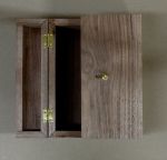
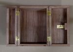
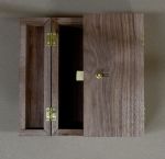
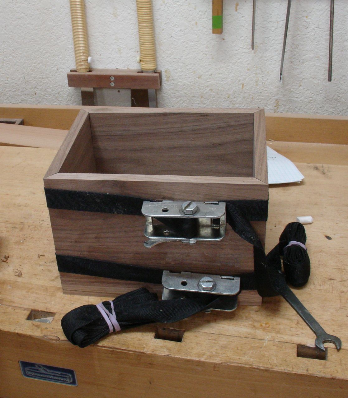
In the meantime, I’ll continue to use this prototype to work out a latch system. If you can picture how the two clamshell lids will close you can imagine the unique situation we’re facing. A perfect solution would be an antique type drawer lock but since these two close on to each other that may not work. I’m partially done designing a drawbar system from brass. As for now, the box with the separated corners has been glued and clamped as a temporary fix to work on the hinge and latching system for the Mystery Box.

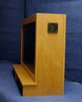
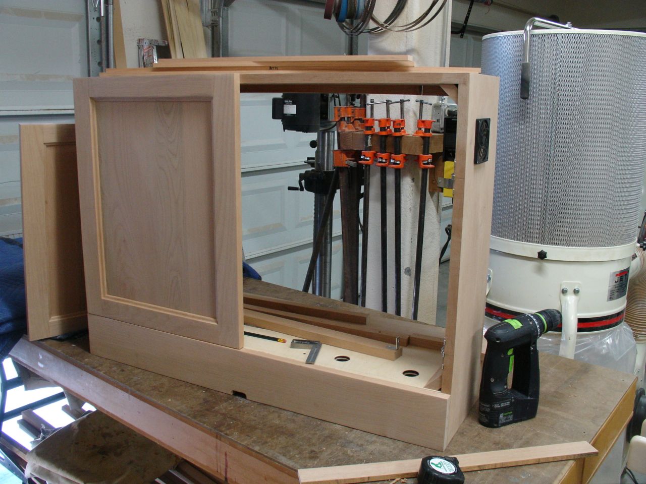
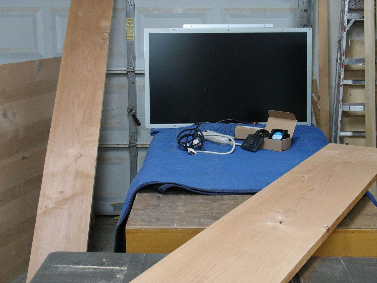
 Here is the completed cabinet for the 31″ computer monitor I’ve been working on. You’ve heard me refer to this project as my “head scratcher” because of the requirements my client had. He knew it would be somewhat tricky but I believe I’ve given him what he wants. That’s always my goal, to give the client more than he thought he’d get. Delivery is next week and I’m anxious to get his reaction to the real thing, not just blog photographs!